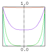
Fig. 1. Skin effect for annealed copper wire with a diameter of 1mm
Current flowing through a cylindrical conductor distributes evenly along the conductor cross-section when the current is a direct current. However, with the increase in frequency, the effect where the current concentrates at the conductor surface and the current density decreases at the center, is known well as the skin effect (footnote 1). For example, Fig. 1 shows the current density in the conductor cross-section of an annealed copper wire with a diameter of 1mm for frequencies 10kHz, 100kHz, 1MHz and 10MHz.

Fig. 1. Skin effect for annealed copper wire with a diameter of 1mm
The x-axis in Fig. 1 is the distance from the conductor center (center of the figure represents the center of the conductor and both ends show the conductor surface), and the y-axis is (internal current density/current density at conductor surface). The red, purple, green and light green lines correspond to the current density in the conductor cross-section for 10kHz, 100kHz, 1MHz and 10MHz respectively. The current density at the center of the conductor decreases from 98% of the surface for 10kHz, to 41% for 100kHz, to 0.4% for 1MHz, and to just 0.00000006% for 10MHz.
What happens in the seven-core conductor in Fig. 2 that is often used as the core conductor in coaxial cables?

Fig. 2 Cross-section of seven-core conductor
Can we think that by the "skin effect" of the twisted wire as a whole, the current concentrates along the circumscribed circle of the twisted wire (shown in red) with an increase in frequency, like a single wire ?
Or, by placing small gaps between the seven conductors, can we decrease the "skin effect" of this seven-core conductor ?
This is the problem.
Obtaining the current distribution of a single cylindrical conductor under high frequency is relatively simple, and the solution is shown below. The current distribution shown in Fig. 1 has been calculated using this equation. However, only the magnitude is shown. Note that the phase of the current also depends on the position. As we get deeper into the conductor from the surface, the phase of the current delays and may even become backward!
  Ir / Ia = I0(sqrt(j)*k*r) / I0(sqrt(j)*k*a)
  Here,
	Ir = current density (A/m^2) at radius r (m)
	Ia = current density at outer surface of conductor (A/m^2)
	a = conductor radius (m)
	j = sqrt(-1)
	k = sqrt(¦Ø*¦Ì*¦Ò)
	w = angular velocity (rad/s)
	   = 2*PI*f
	PI = 3.14159265..
	f = frequency (Hz)
	u = permeability (H/m)
	g = dielectric constant (S/m)
	I0(z) = Modified Bessel Function of First kind of order 0
	I1(z) = Modified Bessel Function of First kind of order 1
Kouichi Hirabayashi, (C) 2001